|
|
|
Categories
|
|
Information
|
|
Featured Product
|
|
|
 |
|
|
There are currently no product reviews.
 ;
Block diagram,play rec block diagram,adjusments, it's a very good well done repair manual.
;
Very clear copy of the philips service manual. Fast delivery. Thank you very much
;
Excellent manual, detailed, very useful! Exactly what I needed, I'd recommend it to all who need it. Although images are scanned easily readable and explicit. A valuable tool product at a price more than modest, take it with confidence and you will not regret it!
;
Clear and complete service manual. Easy now to restore my old Kenwood KD-1500.
Thanks a lot.
;
Thanks for this "hard to find" service manual. This Sony PS212A is a very good turntable that needed to be restored !
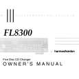
harman/kardon
Service bulletin # 9604 rev1 - October 1998 To: All harman/kardon Service Centers Models: FL8300 Subject: Digital Output Level
Service Bulletin
This is considered a Minor Repair
The Digital Interface Standard recommends D/A converters have a minimum Input sensitivity of 200 mV. In early FL8300 production units, the Digital Output level was 240 mV ±10% peak to peak. Based on our research, we found that some D/A converters require more than 240 mV for intermittent free operation. In the event you receive a FL8300 from a consumer with the a complaint �Intermittent Sound from External D/A converter�, check the serial number in the table below. If the FL8300 has a serial number higher than indicated in the table below, connect a properly working D/A converter to the Digital Output and verify interruption free operation. Also confirm the Digital Output level of the FL8300 is 500 mV ±10% Peak to Peak. If the FL8300 passes these two tests, advise the customer to have their external D/A converter and connecting cables checked. If the FL8300 has a serial number lower than indicated in the table below, perform the following modification: 1) With the unit plugged in and turned on, push the �open/close� button to extend the drawer fully; then turn the unit off and unplug it. 2) Open the top cover (6 screws). 3) Remove output board PCB3 from the rear panel (4 screws). This board can be pulled back and modified without completely removing it from the chassis. 4) Locate resistor R901, it may be a 680 ohm resistor or a jumper wire; replace in either case with a 0.47 uf capacitor h/k part# 5354-474593. 5) Locate R903 and change from 680W to a 4.7kW resistor - h/k part # 3029472970. Re-attach output PCB3 to the unit. 6) Connect a 75 Ohms cable to the digital output jack. Terminate this cable with a 75 Ohm load; connect an oscilloscope to the 75 Ohm termination resistor. While playing a CD, confirm the output of the signal is now 500 mV ±10% peak to peak. 7) Reassemble the FL8300 and test all functions.
Model FL8300 Serial number 120V IN0019-01001 to IN0019-19393 FL8300 IN0019-19394 Serial number 230V IN0020-01001 to IN0020-04500 IN0020-04501 Status May have low digital output for some applications Factory Installed * Action Replace R901 with 0.47 uf mylar capacitor h/k part# 5354-474593 Replace R903 with 4.7k ohm resistor h/k part# 3029472970 NONE REQUIRED
* Factory modification of the FL8300 starting with the serial numbers indicated in the above table consisted of:
R236: 1k Ohm R901: Jumper or 680 Ohm R903: Changed from 680 Ohm to 4.7k Ohm. Digital output level into 75 Ohms: 500 mV ±10% peak to peak.
22
|
|
|
> |
|